Ender 3 Upgrades Pt. 2 (Hero Me Gen5 & PEI Spring Sheet)
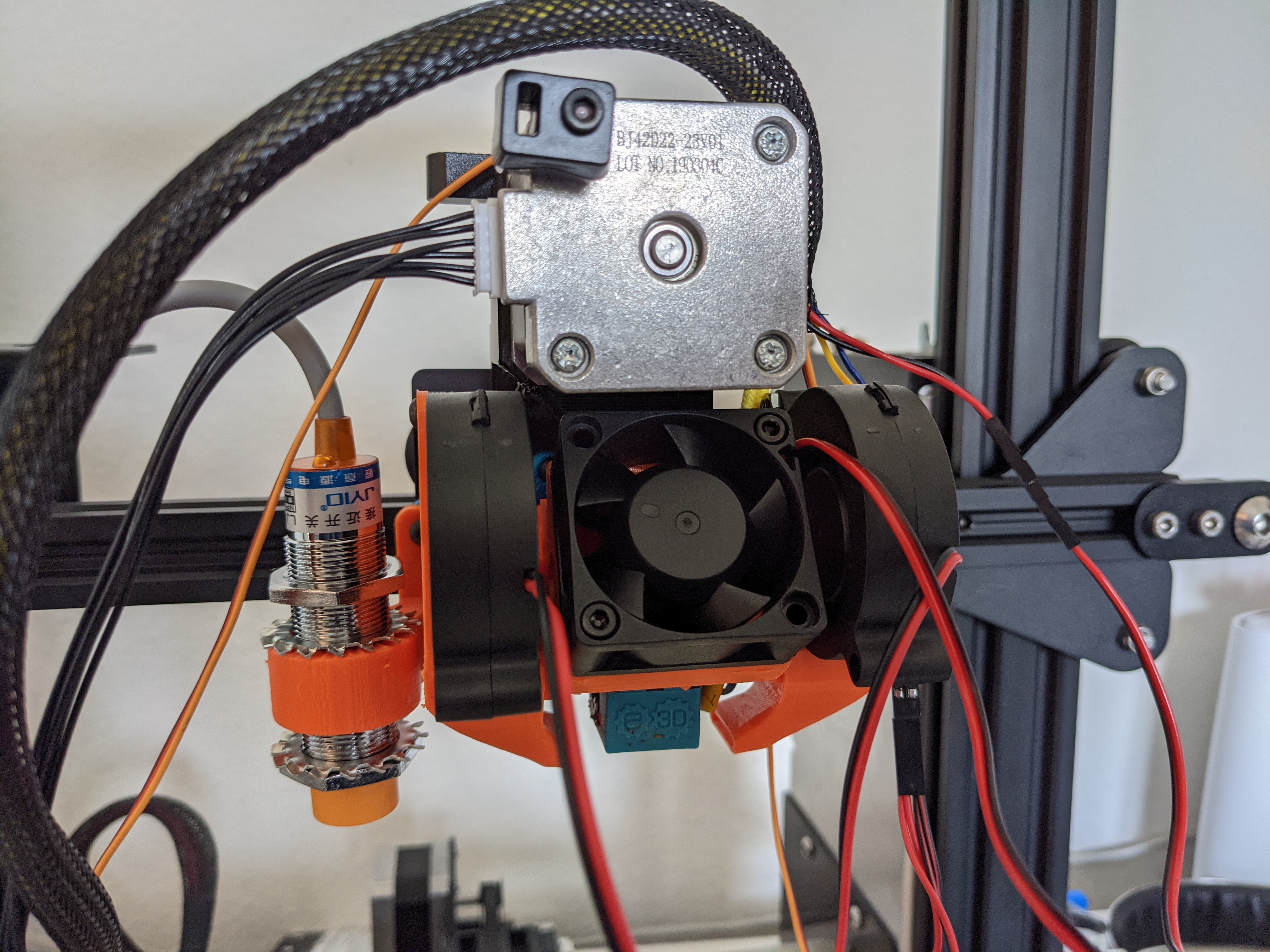
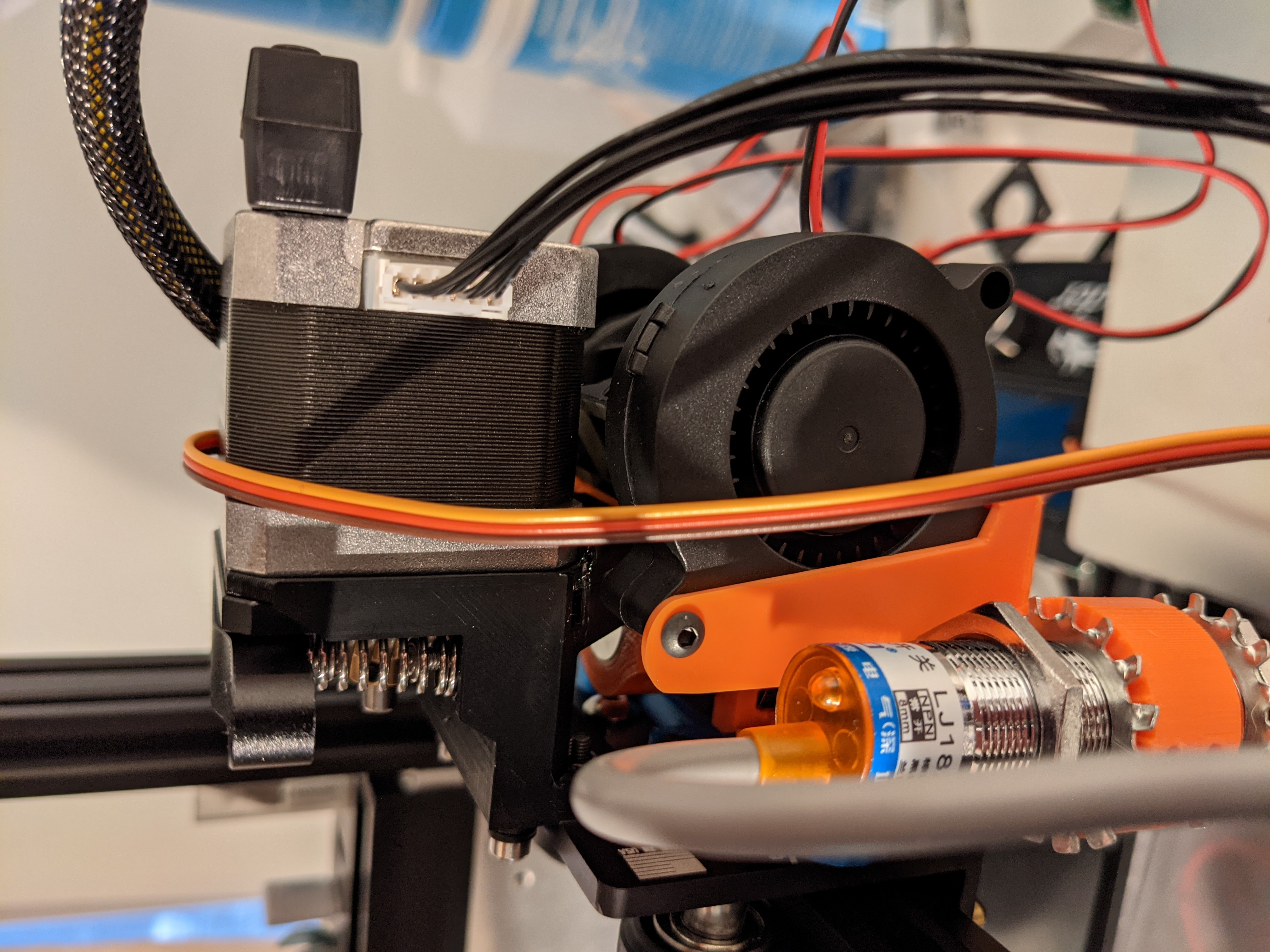
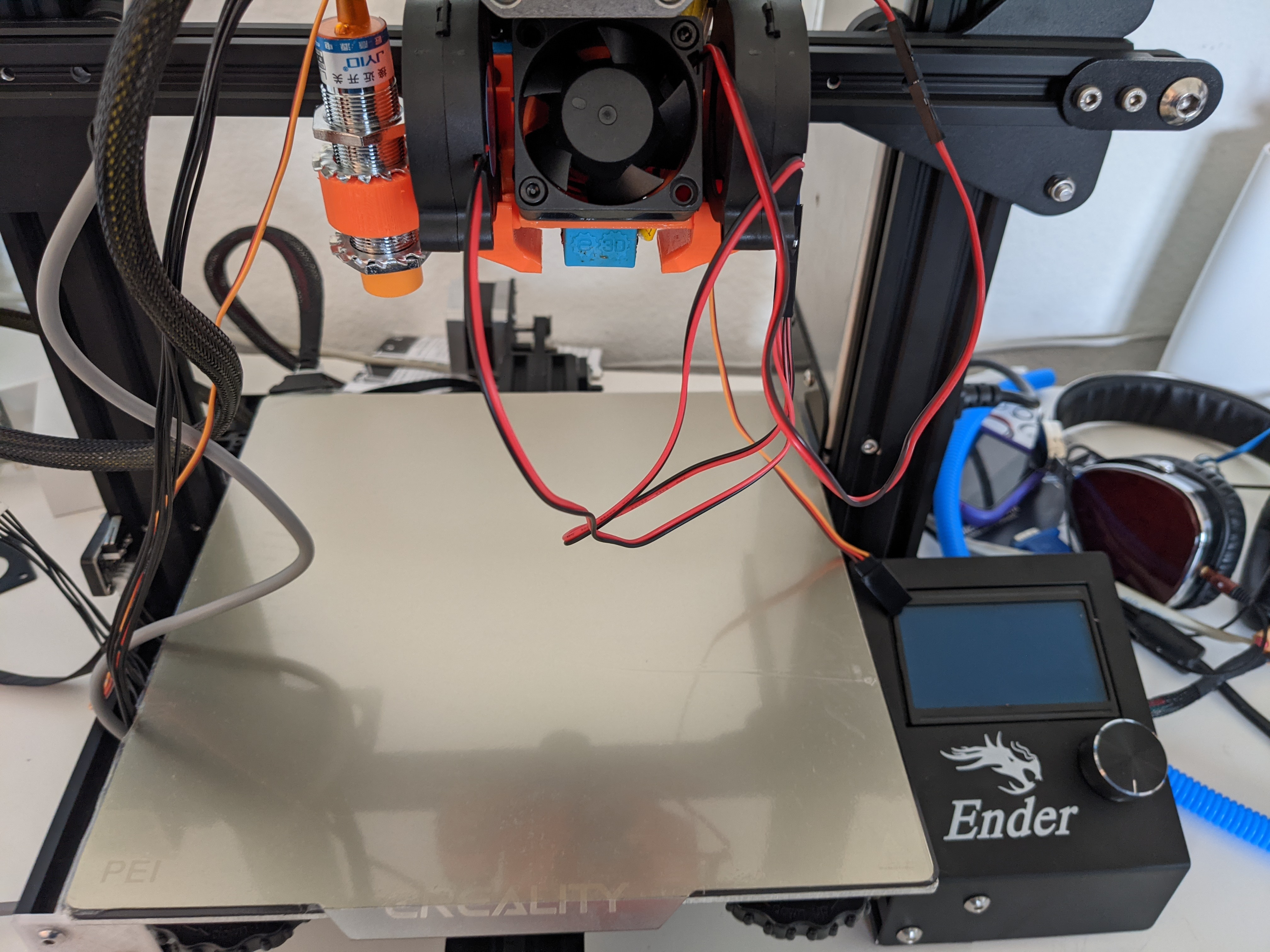
Coming off of my plans to upgrade and tune my Ender 3, I started to work on printing the new hot-end mount and cooling system in the form of the excellent Hero Me Gen5.
Hero Me Gen 5
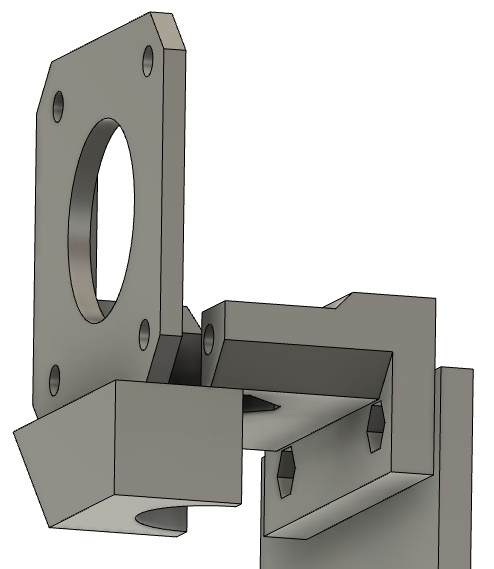
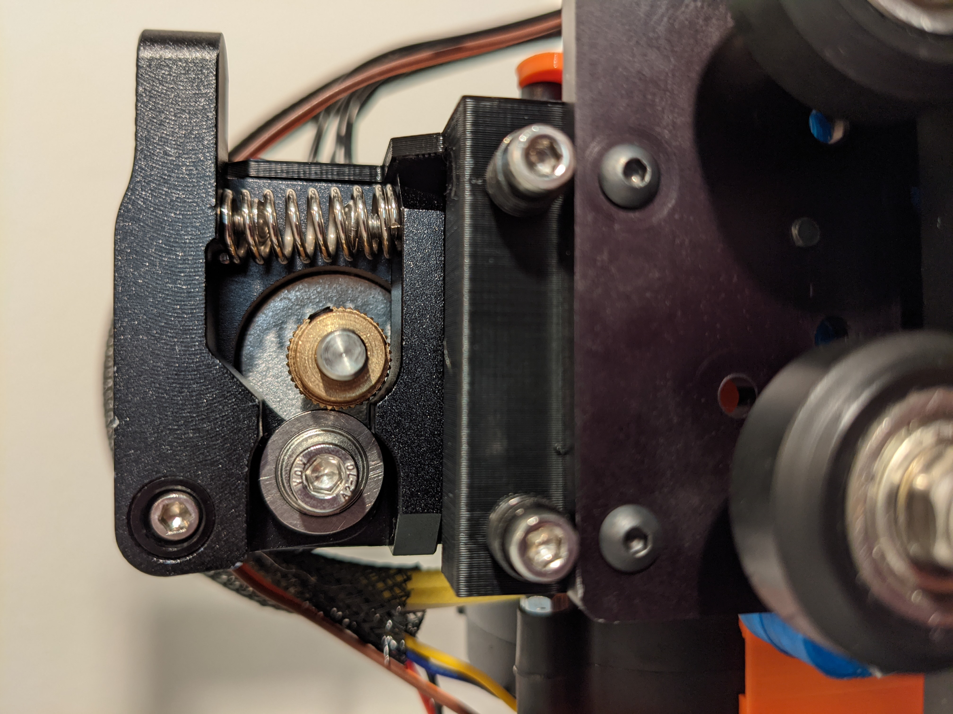
As I also mentioned in that post, I decided to bring my customizations and build up-to-date with a new direct drive mount from PrinterMods, namely the MDD v1.3.
With that in mind, I scoured the very thorough documentation, and watched the assembly video from TeachingTech, at which point I put together the list of parts I needed to print for my combination of components.
HMG5 Parts List;
- PM_v1.3_CR-Ender-E3D-Gantry_Adapter_5B.stl
- PM_Gantry_Clip_5.stl
- Hero_Me_Gen5_Base_3.stl
- HMG5_E3D_V6-Clone_Collar.stl
- HMG5_E3D_V6-Clone_Air_Dam.stl
- 5015_Lightweight_Duct_Standard_Right.stl
- 5015_Lightweight_Duct_Standard_Left.stl
- EZABL_Mount_Medium_18mm.stl
- DD Adapters? Pg. 9 of assembly guide
Notice the last bullet? Well, I’m using the OEM Extruder, so the only apparent match was the PM_OEM_Extruder_adapter.stl. I would discover later, when attempting to assemble my new parts, that this is NOT compatible with the MDD v1.3, which apparently moved the DD extruder mounting points a couple mm closer to the hotend.
After some quick searching, it didn’t appear as though anyone else had solved this problem, tho a handful of comments did appear on the original thingiverse posting for the HMG5. Rather than wait for a solution from the original designer, or the community, I went ahead and designed my own mount which you can find as a remix on thingiverse.
X Gantry
While assembling all of this, it became clear to me that the left and right sides of the X gantry were not level! This almost certainly would have contributed to the bed leveling and first layer adhesion problems I was having!
I measured from the X gantry to the top of the frame, and discovered that the right side (the PSU side, furthest from the Z axis screw) was nearly 1cm HIGHER than the left side. I have no idea how this would have happened, and my expectation is that if anything the right side would “sag” since it isn’t directly supported by a Z screw.
A quick run through the steps in this excellent video got things squared back up and close enough to equal that I can’t detect a difference with the naked eye.
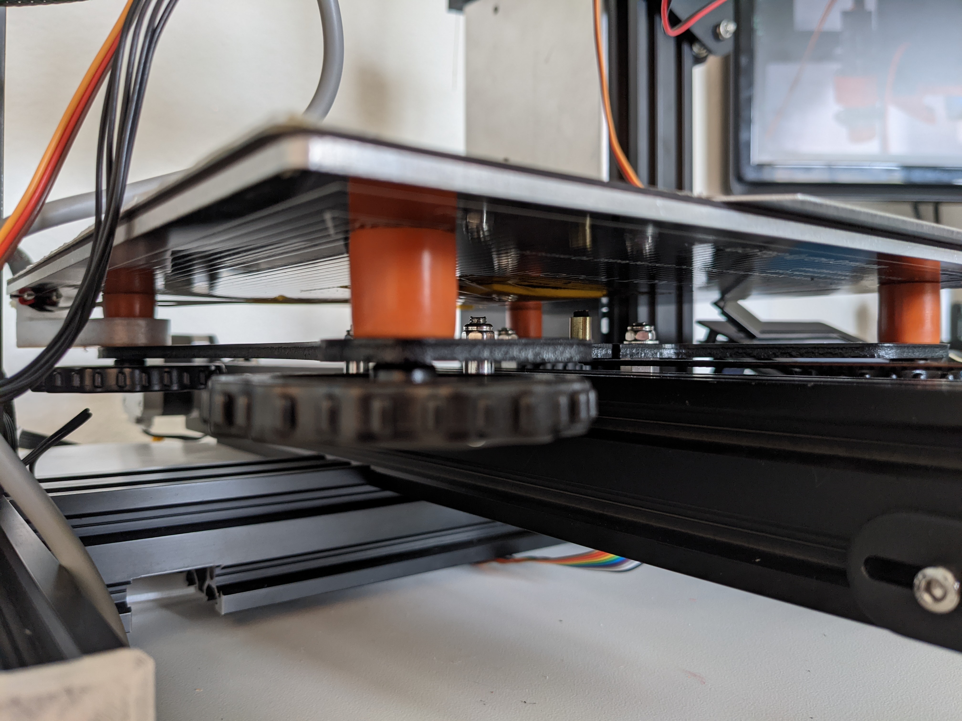
PEI Spring Sheet & solid bed mounts
The final step was to replace the bed leveling springs with solid mounts, and install a new magnetic sheet for a PEI spring sheet.
I removed my glass sheet, and the original magnet on the heated bed. This made way to install the new magnetic sheet, and stick the PEI spring sheet on top of that.
I will still be printing with either the glass, or this new spring sheet, depending on the models and materials I print. I intend to setup different slicer profiles with different z offsets to accommodate for this. More on that in a future post.
Next steps
That covers all of the mechanical upgrades that I had planned. You may notice in the pictures that the wires are a bit of a disaster. This is intentional, since I’m going to tidy those up, and get the wiring for the inductive ABL sensor dialed in as another installment of this series of blog posts. So, keep your eyes peeled here!